It has been a difficult month here. Despite constant problems, I eventually got into my garage for 6 hours on Saturday and 5 on Sunday. Still not good for a "go away and leave me alone, I am in the garage all weekend and will kill anyone who interrupts me!!" weekend where I SHOULD have had at least 8-9 hours both days. But apparently death threats are not taken seriously at my place. I may have to remedy that!

I have also been sidetracked on another exciting project but that is mostly a "late night" thing which costs me sleep but nothing else and is helping to keep me sane!
Anyway......
FINALLY some major progress BUT surprisingly little to "show" for it.
The main upper longerons have been bugging me for quite some time. (since before Christmas, in fact). But the long lead time and many, many rethinks have finally borne fruit, I think.
I finally gave up on bending 2 metres of 1.5 mm aluminium in to a complex U shape with flanges. This has meant that I have had to settle for a slightly off scale fit. The final dimensions are 41.6mm x 30mm x 41.6mm and 18mm flanges, instead of the 38.1 x 38.1 x 38.1 with 20.32mm flanges called out on the GA at Frame 8. A frustrating, to be honest, but necessary compromise. (Imperial.. should be 1.6" x 1.6" x 1.6" with flanges 0.8" but is 1.638" x 1.18" x 1.638" with a 0.72" flanges)
This was achieved by paring down 50mm x50mm x 1.5mm ali tubing and fixing 20mm x 20mm angle aluminium onto it. The rivetting was all able to be placed so that it will not be visible on the finished product..(hidden by Frames, accessories etc).. and the joins on the upper face will be sealed with car "bog". so the pieces will look like a single, folded structure. I’m just hoping that the rectangular profile in the cockpit is not too noticeable against the apparent square profile of the original longeron.
The difference in width was easily accommodated in Supermarine's "fudge factor" in the GAs and line widths etc. The flanges are a tiny bit thicker than called out for but easily fit and will add extra strength. I’m not getting any younger and want to be able to place full weight on the structure to lower myself in!
The lower longerons are also not correct and are, in fact, quite a bit different. But they are not really visible in the cockpit and I can always make inserts to go over the top where they are seen. The more compact design will add strength to the base of the frames too, reducing the “cut-out" size and increasing the area of the Frame faces at the joins.…again, desirable as there is no engine area adding strength up front, no wings on the side and no tapered tail section adding it at the rear. It will also allow wheels to be attached to them to make the cockpit mobile.
And while on the subject of compromise… I have to admit that I have decided to base ALL of the Frame widths on Frame 8. So there will not be the approximately ¾“ taper between Frames 8 and 11 that is on the real aircraft. This simplifies construction, skinning AND importantly, the rear slide of the Canopy! So sue me

I don’t think it will be perceptible to the eye…at least I hope not!
Sorry about the low quality pictures..will get some improved ones as we go along.
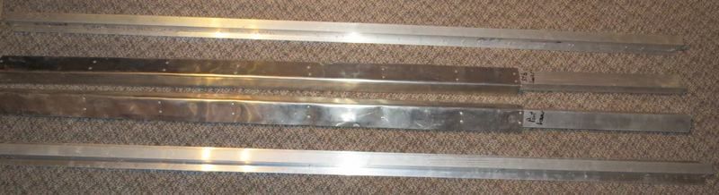
The four longerons. Thickest lower, thinnest upper.
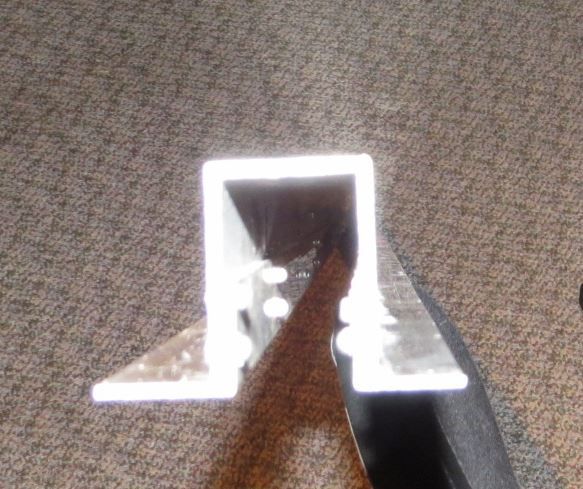
The profile of the main upper. The flanges on the bottom need to be slightly bent out to fit on the frames. A job for later. I wish I had noticed before I joined them. It would have been easier to bend them to less than 90deg before attachment
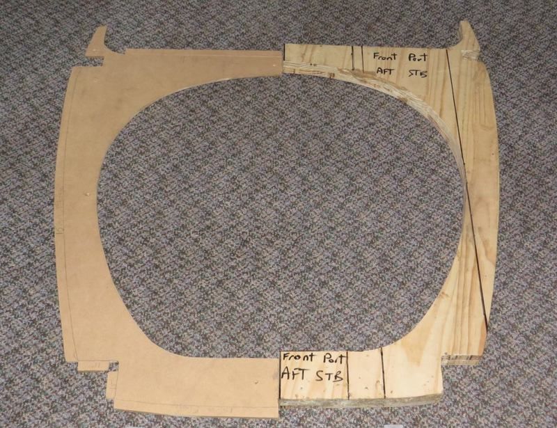
And lastly, the final pattern for the sheet ali of Frame 8, including the overhang for the flanges and the Former for bending the sheet. I am learning ALL about preparation!! A raw pattern in wood off the blown up and printed GA, another with flange allowance, marked out from the original pattern and flanges measured and drawn in and thirdly, a Former routed from heavier wood from the original light wood pattern ex flanges… A printed paper pattern, full size and three patterns for each Frame! And I still need to cut undersized holes in the Former and route 45deg out to size for forming the lightening holes.
For reference, Frame 8 will be just about 34" wide (864mm) and just under 30" high.