
The eraser idea is quite good. I was thinking last night when I read your post is that you need some sort of resistance that is positive, and then gives way.
Like two raised pieces of a hard, durable plastic (equal and opposite sections of a sphere? ) on either side of the gate that would resist and then give way as you move past them into WEP.
P-51D cockpit build
Re: P-51D cockpit build
Thanks Broseph and Jacques
The eraser has worked best so far but I am still looking at other options. By limiting/enlarging the cut I can somewhat control the resistance.
There is not much area to work with at the WEP itself. I am still considering a bump stop near the green switch that would require a slight movement to the right to let the throttle lever pass and continue to the green switch. The issue with this is the limited slot at the top of the face plate where the throttle lever traverses. See pic below.
Please keep the ideas coming!
Thanks
Ed

If at first you do succeed, try not to look too surprised!
-
Lewis - A2A

- A2A Lieutenant Colonel
- Posts: 33319
- Joined: 06 Nov 2004, 23:22
- Location: Norfolk UK
- Contact:
Re: P-51D cockpit build
Could be a ball bearing/spring type system that is sprung loaded together and the throttle slides between them to move into WEP?Jacques wrote:The eraser idea is quite good. I was thinking last night when I read your post is that you need some sort of resistance that is positive, and then gives way.
Like two raised pieces of a hard, durable plastic (equal and opposite sections of a sphere? ) on either side of the gate that would resist and then give way as you move past them into WEP.
I love this thread, the ideas are awesome
cheers,
Lewis
A2A Facebook for news live to your social media newsfeed
A2A Youtube because a video can say a thousand screenshots,..
A2A Simulations Twitter for news live to your social media newsfeed
A2A Simulations Community Discord for voice/text chat
A2A Youtube because a video can say a thousand screenshots,..
A2A Simulations Twitter for news live to your social media newsfeed
A2A Simulations Community Discord for voice/text chat
-
Piper_EEWL

- Chief Master Sergeant
- Posts: 4544
- Joined: 26 Nov 2014, 14:14
- Location: Germany
Re: P-51D cockpit build
Maybe a spring that also acts as the wire. Once you push the throttle trough it'll give you resistance and when getting the throttle back out it'll I've the wire back into place.
Something like this maybe
http://eagle6.co.uk/shop/catalog/produc ... ck-series/
They use them on motorcycles too. The spring could be hidden under the aluminum plate and only one of the two ends can be seen as the "wire".
I hope you get what I mean. I feel like my explanation is not very clear but I can't come up with something better at the moment. Sorry
Great stuff! Love the detail!
B377&COTS, J3 Cub, B-17G, Spitfire, P-40, P-51D, C172, C182, Pa28, Pa24, T-6 Texan, L-049&COTS, Bonanza V35B
Re: P-51D cockpit build
Hi everyone
Today’s word of the day is compromise.
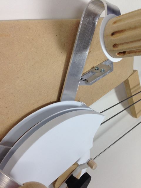
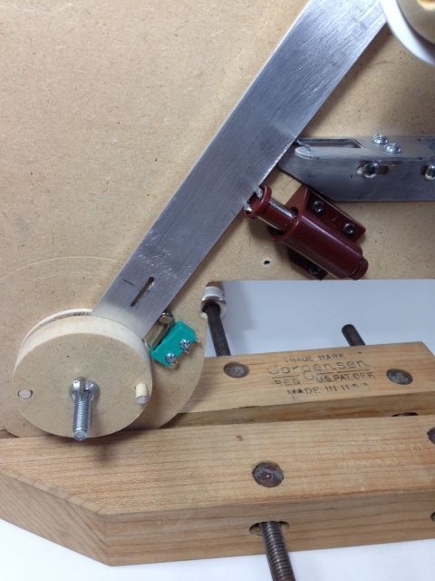
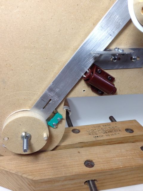
As I tried different options for the WEP device I decided that I could not hide all of the components and still get the feel I wanted. So today I mounted a cabinet door mechanism. In case you are not familiar with how they work it is spring loaded and stored in the compressed position. When you want to open the door you push the door in a little and the spring unlocks popping the door open.
I have mounted mine so the spring will be in the out position. This gives a firm stopping point but when pushed will compress and lock closed allowing the lever to activate the green switch. This will be partially hidden by the throttle face plate. Also I’m hoping when it is painted the same color as the pit side it will blend in and not be too noticeable.
For the breakable wire I tied a knot in metal stranded wire and fed it from under the bracket through the hole on the pit side. It then spans the gap and just goes into the outer hole but is not secured. When the throttle lever hits the wire it is pulled from the outer hole and pushed aside. To replace the wire I just tuck it back in to the outer hole.
The first pic shows the lever just making contact with the stop and the green switch but not compressing either one. The second pic shows the lever has pushed the wire aside and compressed the spring device and activated the green switch.
Thank you everyone for your suggestions on this component.
Ed
Today’s word of the day is compromise.
As I tried different options for the WEP device I decided that I could not hide all of the components and still get the feel I wanted. So today I mounted a cabinet door mechanism. In case you are not familiar with how they work it is spring loaded and stored in the compressed position. When you want to open the door you push the door in a little and the spring unlocks popping the door open.
I have mounted mine so the spring will be in the out position. This gives a firm stopping point but when pushed will compress and lock closed allowing the lever to activate the green switch. This will be partially hidden by the throttle face plate. Also I’m hoping when it is painted the same color as the pit side it will blend in and not be too noticeable.
For the breakable wire I tied a knot in metal stranded wire and fed it from under the bracket through the hole on the pit side. It then spans the gap and just goes into the outer hole but is not secured. When the throttle lever hits the wire it is pulled from the outer hole and pushed aside. To replace the wire I just tuck it back in to the outer hole.
The first pic shows the lever just making contact with the stop and the green switch but not compressing either one. The second pic shows the lever has pushed the wire aside and compressed the spring device and activated the green switch.
Thank you everyone for your suggestions on this component.
Ed
If at first you do succeed, try not to look too surprised!
Re: P-51D cockpit build
That is probably the best solution to give you that positive feedback while maintaining simplicity. Very nice, Ed!!
-
Piper_EEWL
- Chief Master Sergeant
- Posts: 4544
- Joined: 26 Nov 2014, 14:14
- Location: Germany
Re: P-51D cockpit build
Very nice solution. I like the simplicity. Good engineering!
B377&COTS, J3 Cub, B-17G, Spitfire, P-40, P-51D, C172, C182, Pa28, Pa24, T-6 Texan, L-049&COTS, Bonanza V35B
Re: P-51D cockpit build
Thanks guys.
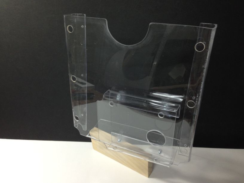
After following the conversation on this forum about the map case I decided to add it to my pit. Why not, this pit will never be complete anyway!
It had been left out because I didn't have information but Bomber_12th supplied great pictures and plans so here we go.
I chose 1/8 acrylic sheet instead of metal or wood. However, I would probably use metal if I had to do it again. Heating and bending plastic is not an exact science for me.
Well, here it is. Not easy to build or photograph. Hopefully when painted it will look the part.
Thanks for looking.
Ed
If at first you do succeed, try not to look too surprised!
Re: P-51D cockpit build
Hello everyone
In case you haven’t noticed I’ve added a new topic “P-51 and FSX information neededâ€Â. It will not replace this thread. I'm requesting your help identifying popular FSX commands for my pit. Please check it out and offer your suggestions.
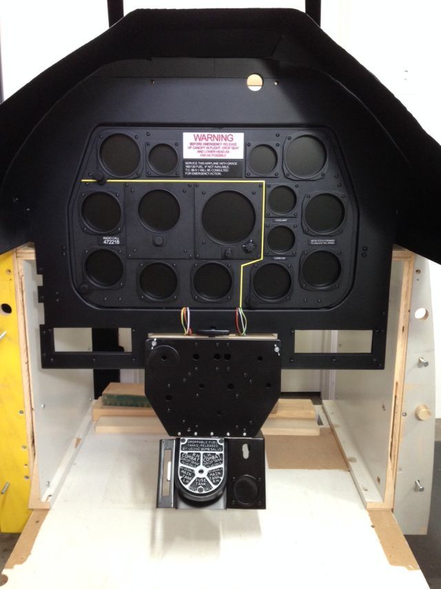
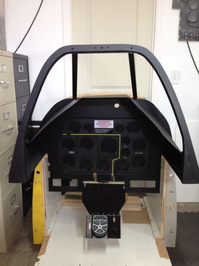
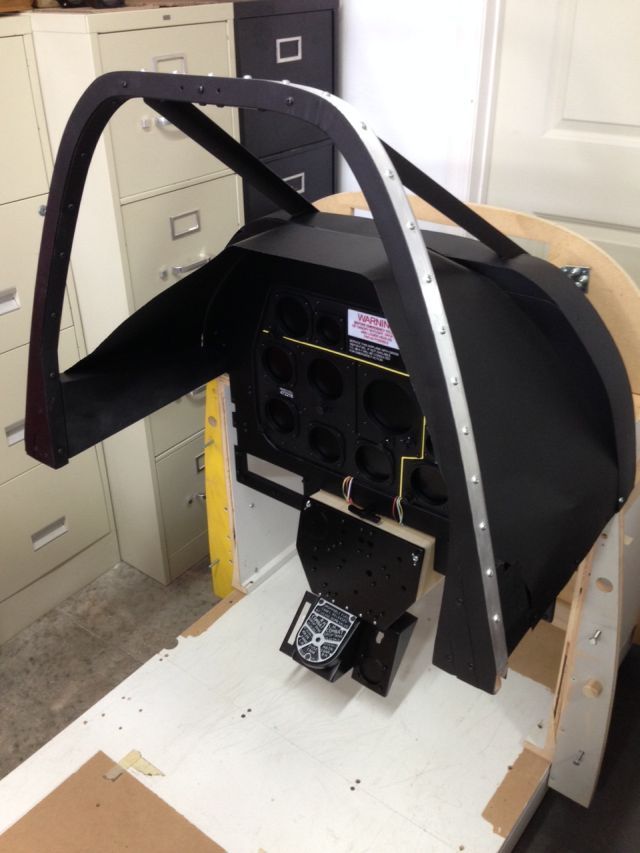
We finally got some weather where I could get some paint applied although I do believe I got more paint on me than the parts. I’ll add more of those pictures later as I get more work completed.
But today I had one of those “let’s see what this thing is going to look like†episodes. You know, where you hold pieces together to see what is working or not.
In these pictures you can see the LCD screen and MIP mounted in its frame along with and the windshield frame. I added .020 styrene to the edges of the MIP and painted it flat black. The styrene slides under the edges of the MIP frame holding the MIP in place. The wires will be out of sight in grooves in the MIP frame.
Thanks for looking.
Ed
In case you haven’t noticed I’ve added a new topic “P-51 and FSX information neededâ€Â. It will not replace this thread. I'm requesting your help identifying popular FSX commands for my pit. Please check it out and offer your suggestions.
We finally got some weather where I could get some paint applied although I do believe I got more paint on me than the parts. I’ll add more of those pictures later as I get more work completed.
But today I had one of those “let’s see what this thing is going to look like†episodes. You know, where you hold pieces together to see what is working or not.
In these pictures you can see the LCD screen and MIP mounted in its frame along with and the windshield frame. I added .020 styrene to the edges of the MIP and painted it flat black. The styrene slides under the edges of the MIP frame holding the MIP in place. The wires will be out of sight in grooves in the MIP frame.
Thanks for looking.
Ed
If at first you do succeed, try not to look too surprised!
-
Lewis - A2A
- A2A Lieutenant Colonel
- Posts: 33319
- Joined: 06 Nov 2004, 23:22
- Location: Norfolk UK
- Contact:
Re: P-51D cockpit build
Holy moly thats amazing!
A2A Facebook for news live to your social media newsfeed
A2A Youtube because a video can say a thousand screenshots,..
A2A Simulations Twitter for news live to your social media newsfeed
A2A Simulations Community Discord for voice/text chat
A2A Youtube because a video can say a thousand screenshots,..
A2A Simulations Twitter for news live to your social media newsfeed
A2A Simulations Community Discord for voice/text chat
-
Piper_EEWL
- Chief Master Sergeant
- Posts: 4544
- Joined: 26 Nov 2014, 14:14
- Location: Germany
Re: P-51D cockpit build
Looks awesome!
Thanks for sharing
Thanks for sharing
B377&COTS, J3 Cub, B-17G, Spitfire, P-40, P-51D, C172, C182, Pa28, Pa24, T-6 Texan, L-049&COTS, Bonanza V35B
Re: P-51D cockpit build
Thanks guys.
It has looked like a bunch of parts on a table and I just had to see how these parts and their colors would match. Now I need to start adding the lettering for all of the panels.
Lewis, is there a specific font you guys used when making the MIL pit? If not I will just have to find something close.
Take care
Ed
If at first you do succeed, try not to look too surprised!
-
DHenriques_

- A2A Chief Pilot
- Posts: 5711
- Joined: 27 Mar 2009, 08:31
- Location: East Coast United States
Re: P-51D cockpit build
This work could easily surpass the original mockup done by NA Aviation. I simply can't believe the quality what you are accomplishing here.Raceguy wrote:Hello everyone
In case you haven’t noticed I’ve added a new topic “P-51 and FSX information neededâ€Â. It will not replace this thread. I'm requesting your help identifying popular FSX commands for my pit. Please check it out and offer your suggestions.
We finally got some weather where I could get some paint applied although I do believe I got more paint on me than the parts. I’ll add more of those pictures later as I get more work completed.
But today I had one of those “let’s see what this thing is going to look like†episodes. You know, where you hold pieces together to see what is working or not.
In these pictures you can see the LCD screen and MIP mounted in its frame along with and the windshield frame. I added .020 styrene to the edges of the MIP and painted it flat black. The styrene slides under the edges of the MIP frame holding the MIP in place. The wires will be out of sight in grooves in the MIP frame.
Thanks for looking.
Ed
Dudley Henriques
Re: P-51D cockpit build
Dudley, thank you for your kind words!
Take care
Ed
Take care
Ed
If at first you do succeed, try not to look too surprised!
Re: P-51D cockpit build
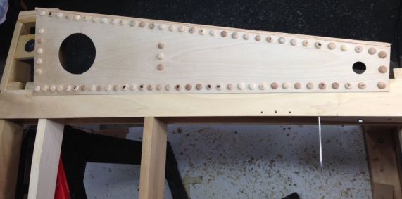
Hello everyone
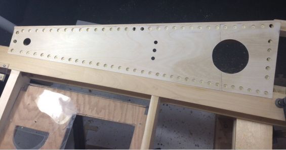
Well, today was riveting, literally.
Yesterday I had cut and installed the panels on each cockpit side under the canopy rail. Today I made “rivetsâ€Â, drilled holes for them and secured them in place.
These are not real rivets but wood plugs. I flattened the top of each one, 80 per side if you are counting, to simulate real rivets. I did this by drilling a hole the size of the plug base in a piece of scrap wood then placed a plug in the wood and eased the plug into the sanding disk on my belt/disk sander.

This worked pretty well for most of the plugs but there were “issues†with a few. Have you ever seen a batting cage where they launch the balls at you by passing them between two spinning wheels? Or maybe a cartoon where something is fired off and ricochets around a room making a pinging sound with each object it strikes? Yep, that happened with a few. The first one scared the @&%# out of me. After that I expected more to launch and was somewhat ready. I found all but one and it may still be bouncing around the shop!!! Yes, I was wearing safety glasses.
The first pic shows a cockpit side with the holes drilled and the second shows the rivets installed.
Thanks for looking.
Ed
Well, today was riveting, literally.
Yesterday I had cut and installed the panels on each cockpit side under the canopy rail. Today I made “rivetsâ€Â, drilled holes for them and secured them in place.
These are not real rivets but wood plugs. I flattened the top of each one, 80 per side if you are counting, to simulate real rivets. I did this by drilling a hole the size of the plug base in a piece of scrap wood then placed a plug in the wood and eased the plug into the sanding disk on my belt/disk sander.
This worked pretty well for most of the plugs but there were “issues†with a few. Have you ever seen a batting cage where they launch the balls at you by passing them between two spinning wheels? Or maybe a cartoon where something is fired off and ricochets around a room making a pinging sound with each object it strikes? Yep, that happened with a few. The first one scared the @&%# out of me.
The first pic shows a cockpit side with the holes drilled and the second shows the rivets installed.
Thanks for looking.
Ed
If at first you do succeed, try not to look too surprised!
Who is online
Users browsing this forum: No registered users and 37 guests